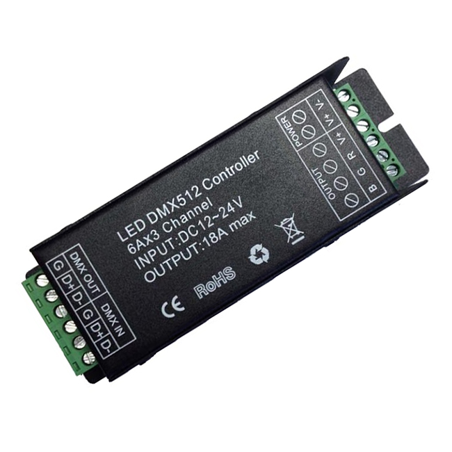
HX-SZ200-DECODER(6P)
-
Product Introduction:
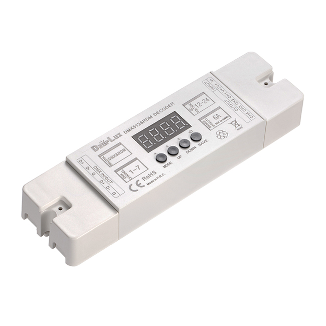
LED DMX512 Decoder DMX512 decoder adopts the advanced micro control unit. It can receive the DMX-512 standard digital control signal which is internationally widely used. It changes the signal into PWM control signal to actuate the LED lamp. It can also connect the DMX digital master to change the light color or dynamic effect.
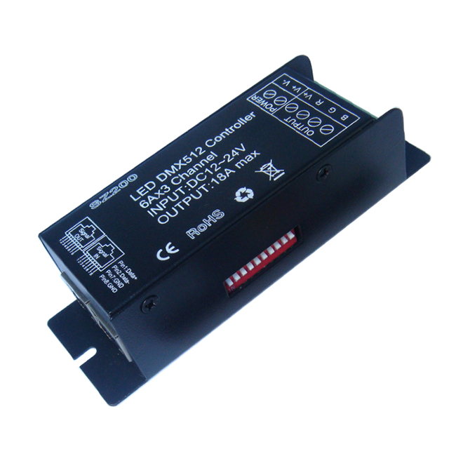
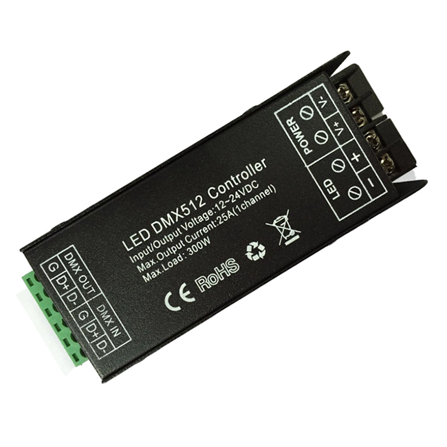
Product Details
Product Feature
Interface Specifications
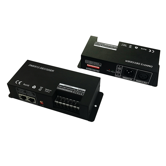
DMX input/output interface:
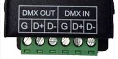
Adopt screw terminals.
Address code and set feature service interface:
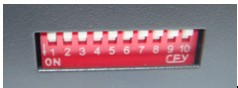
Adopt 10-bit side of the dial-type DIP switch.
Power and load interface:
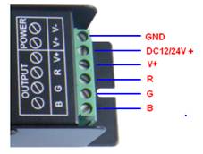
Adopt screw terminals.
Direction for use
This product is in compliance with DMX512 protocol, compatible autoindex addressing and manual establishment address.
Each DMX512 decoder occupies 3 DMX addresses, adopt DIP switch to set up address: When set up the address via DIP switch, the 10th DIP switch bit is “off” status, and other 9 DIP switch(1-9) bits are binary value code switch, which are used to set up the DMX starting address code. The first DIP switch’s bit is the lowest order bit, and the ninth’s is the highest order bit. That can set up 511 address codes. The DMX starting address code = (equal to ) sum of 1st to 9th bit. If move down the DIP switch (“ON” set as “1”), you can get the Bit value of this DIP switch. If move up (set as “0”), the bit value is 0. For example: if you want to set up DMX starting address code for 73, you should move down the 7th, 4th, and 1st DIP switch as “1”, and others as “0”, Then the bit value sum of 1st to 9th is 64+8+1. That is to say, the DMX512 starting address code is 73. (The correspondence dials code position is as follows)
To choose the channel from the Dial in-line Package (DIP) Switch:
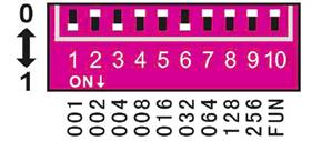
Figure 1
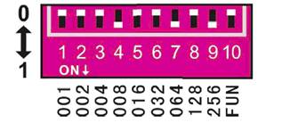
Figure 2
The function outside of the DMX
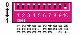 The DIP switch’s 10th bit is “FUN”, for built-in function key. When “FUN”=”OFF”, is for DMX decoder function. This is used to adopt DMX signal. When “FUN”=”ON”, the test function like figure 3:
1-9 switch OFF: black
Switch 1=ON: red
Switch 2=ON: green
Switch 3=ON: blue
Switch 4=ON: yellow
Switch 5=ON: purple
Switch 6=ON: cyan
Switch 7=ON: white Figure 3
Switch 8=ON: Seven-color jumpy changing (8 grades of speeds are available)
Switch 9=ON: All-color gradual changing (8 grades of speeds are available)
1-7 switch OFF: 0 grades of speeds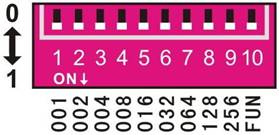
- As a constant voltage decoder, accept international popular DMX512 standard digital control signal, convert it to the PWM signal to drive LED lamps, applicable to a variety of constant voltage LED lamps, such as RGB LED module, lights, string lights, etc.
- DMX decoder can be controlled by DMX master, and the decoder can connect the signal line to continue to expand the channels up to 512, eventually be able to achieve more change in effect.
- When used alone, it also can be used as a RGB controller, with 9 modes in total, can be chosen by the DIP switch.
- In order to achieve synchronization of more LED lamps, RGB amplifier can be used.
- There channels for RGB output, maximum current of 6A/CH.
- 2-year warranty.
| Working temperature | -20-60в„ғ |
| Supply voltage | DC12~24V |
| Output | 3 channels |
| Connecting mode | common anode |
| External dimension | L127*W42*H33 (mm) |
| Packing size | L135*W55*H40 (mm) |
| Net weight | 150g |
| Gross weight | 170g |
| Output gray | 256 levels пјҲRGB eachпјү |
| Output current | <6A(each channel) |
| Output power | 5V:<90W, 12V:<216W, 24V:<432W |
| Control standard | DMX512 |
| PWM frequency | 7.8KHz |
DMX input/output interface:
Adopt screw terminals.
Address code and set feature service interface:
Adopt 10-bit side of the dial-type DIP switch.
Power and load interface:
Adopt screw terminals.
Direction for use
This product is in compliance with DMX512 protocol, compatible autoindex addressing and manual establishment address.
Each DMX512 decoder occupies 3 DMX addresses, adopt DIP switch to set up address: When set up the address via DIP switch, the 10th DIP switch bit is “off” status, and other 9 DIP switch(1-9) bits are binary value code switch, which are used to set up the DMX starting address code. The first DIP switch’s bit is the lowest order bit, and the ninth’s is the highest order bit. That can set up 511 address codes. The DMX starting address code = (equal to ) sum of 1st to 9th bit. If move down the DIP switch (“ON” set as “1”), you can get the Bit value of this DIP switch. If move up (set as “0”), the bit value is 0. For example: if you want to set up DMX starting address code for 73, you should move down the 7th, 4th, and 1st DIP switch as “1”, and others as “0”, Then the bit value sum of 1st to 9th is 64+8+1. That is to say, the DMX512 starting address code is 73. (The correspondence dials code position is as follows)
To choose the channel from the Dial in-line Package (DIP) Switch:
| Number | 1 | 2 | 3 | 4 | 5 | 6 | 7 | 8 | 9 | 10 |
| Weight number | 1 | 2 | 4 | 8 | 16 | 32 | 64 | 128 | 256 | FUN |
- Example 1:
Figure 1
- Example 2:
Figure 2
The function outside of the DMX
- Control with DIP switch
- Test function:
The DIP switch’s 10th bit is “FUN”, for built-in function key. When “FUN”=”OFF”, is for DMX decoder function. This is used to adopt DMX signal. When “FUN”=”ON”, the test function like figure 3:1-9 switch OFF: black
Switch 1=ON: red
Switch 2=ON: green
Switch 3=ON: blue
Switch 4=ON: yellow
Switch 5=ON: purple
Switch 6=ON: cyan
Switch 7=ON: white Figure 3
Switch 8=ON: Seven-color jumpy changing (8 grades of speeds are available)
Switch 9=ON: All-color gradual changing (8 grades of speeds are available)
- Speed choice of jumpy changing and gradual changing’s effect:
1-7 switch OFF: 0 grades of speeds
Switch 1=ON: 1 grade of speeds
Switch 2=ON: 2 grades of speeds
Switch 3=ON: 3 grades of speeds
Switch 4=ON: 4 grades of speeds
Switch 5=ON: 5 grades of speeds
Switch 6=ON: 6 grades of speeds
Switch 7=ON: 7 grades of speeds (maximum speed)
Figure 4
 As figure 4, when all switches are “ON” at the same time, the more value is taken as final. The state of decoder is gradual changing of test function. Its variable speed is 7. In addition, when signal indicator (green) blinks slowly, it runs the built-in program effectiveness of decoder. When the decoder receives the DMX signal, signal indicator will flash rapidly.
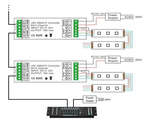
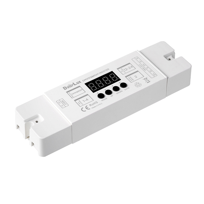
Typical Application
Be used as a DMX512 decoder with DMX512 master:
Product information for placing order
Switch 2=ON: 2 grades of speeds
Switch 3=ON: 3 grades of speeds
Switch 4=ON: 4 grades of speeds
Switch 5=ON: 5 grades of speeds
Switch 6=ON: 6 grades of speeds
Switch 7=ON: 7 grades of speeds (maximum speed)
Figure 4
As figure 4, when all switches are “ON” at the same time, the more value is taken as final. The state of decoder is gradual changing of test function. Its variable speed is 7. In addition, when signal indicator (green) blinks slowly, it runs the built-in program effectiveness of decoder. When the decoder receives the DMX signal, signal indicator will flash rapidly.Typical Application
Be used as a DMX512 decoder with DMX512 master:
Product information for placing order
| Product name | Item number |
| DMX512 Decoder | HX-SZ200-DECODER(6P) |
Product Video
Data download

Keywords:гҖҖжҺ§еҲ¶еҷЁ гҖҖled гҖҖи°ғ гҖҖHX-SZ600-TOUCH гҖҖHX-SZ600- гҖҖHX-RFBT002-RGB
 Jane-Hoion