HX-DR02
-
Product Introduction:
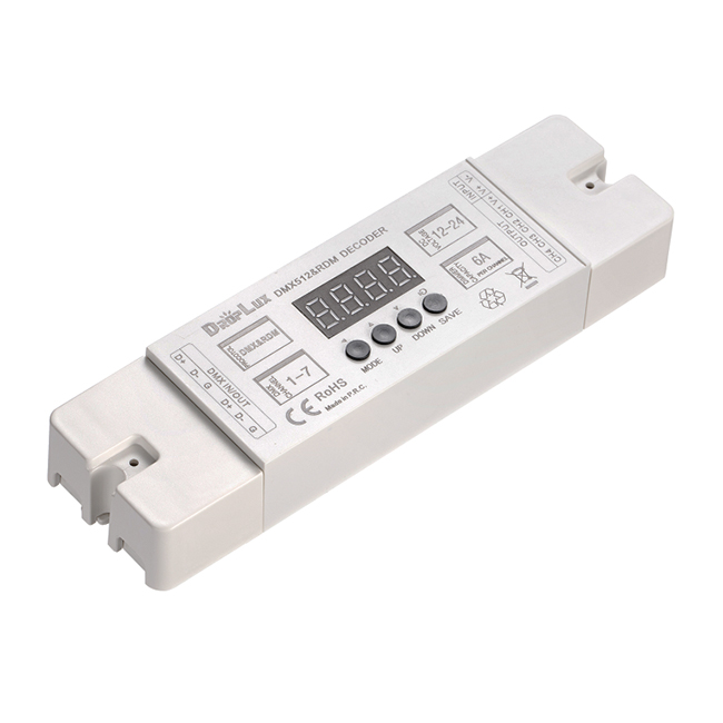
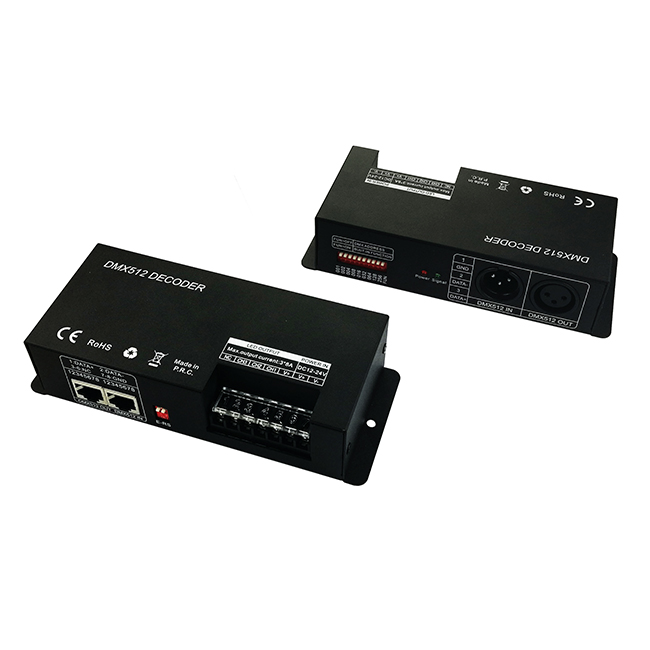
DMX512/RDM Master HX-DR02 is the DMX / RDM master control, supports DMX512 and RDM protocols, and outputs DMX / RDM signals to DMX / RDM decoders; supports the selection of 4 modes: Single color / CCT / RGB / RGBW; users can choose different change mode and change speed for different output types, also can identify the number of devices and change the device address through the RDM function of the controller.
Product Details
Product Features
Dimensions

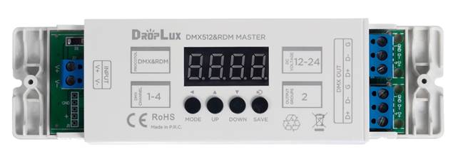
Interface Specifications

Use Instruction
1. Basic settings
In the power-on state, you can directly perform "basic settings", including control settings of mode / speed / brightness.
1) Mode setting
Turn on the power or press the "MODE" key briefly, when the digital tube displays Hxxx (xxx is determined by the effect), enter the setting page of mode. Press the "UP" / "DOWN" keys to set the effect. The effect is shown in the table below. Then press "SAVE" key to save and finish the operation(display SAVE 1 second and return to Hxxx).
2) Speed setting
By short pressing the "MODE" key, when the digital tube displays Sxxx (xxx is 000-255), enter the setting page of speed. Set the effect speed by short pressing the "UP" and "DOWN" keys. Then press the "SAVE" key to save and finish the operation (display SAVE for 1 second and return to Sxxx).
3) Brightness setting
By short pressing the "MODE" key, when the digital tube displays bxxx (xxx is 010-255), enter the setting page of brightness. Set the effect brightness by short-pressing (long-pressing the address quickly) "UP" and "DOWN" keys. Then press "SAVE" key to save and finish the operation (display SAVE 1 second and return to bxxx).
2. Advanced settings
In the Off state, press and hold the "UP" and "DOWN" keys for 2 seconds to enter the "Advanced Settings", can achieve the number of pixels and output type settings.
1) Set the number of pixels (number of devices)
By short pressing the "MODE" key, when the digital tube displays Pxxx (xxx for RGB is 005-170, RGBW for xxx is 005-128, CCT for xxx is 005-256, monochrome for xxx is 005-512), enter the setting The number of pixels. Select by short pressing the "UP" and "DOWN" keys, the minimum setting is 10. After setting, press the "SAVE" key (display SAVE 1 second and return to Hxxx) to save and exit the advanced settings.
2) Set the output type (PH01 is RGB, PH02 is RGBW, PH03 is CCT, and PH04 is monochrome).
By short pressing "MODE" key, when the digital tube displays PHxx (xx is 01-04), enter to set the output type. Select by short pressing the "UP" and "DOWN" keys. After setting, press the "SAVE" key (display SAVE 1 second and return to Hxxx) to save and exit the advanced settings.
Attachment: DR02 output type setting and DR01 decoding type setting coordination table
3. RDM function and instructions
In the power-on state, long press the "SAVE" button for about 2 seconds to enter the RDM function mode, you can achieve the search and address settings of the decoder, long press the "SAVE" button for 2 seconds to save and exit the RDM function after operation.
1) Search the decoder device through DR02
In the RDM function state, short press the "MODE" key, the digital tube displays Lxxx (xxx is 000-128, representing the number of decoders found). L000 means no device was found. For example, L032 means 32 decoders have been searched. At this time, by short pressing the "UP" and "DOWN" keys on the main control, the value on the digital display will increase or decrease accordingly, and at the same time, the load light on the decoder at the corresponding address will flash 2 times to confirm The current decoder position is Lxxx (xxx is 001-032, because only 32 devices are found). If the LED displays L008, the load light of the 8th decoder will flash twice.
2) Set the address of the decoder through DR02 (should be after the search and positioning operation; here L008 is used as an example for further explanation.)
After finding the L008 decoder (the load light of the L008 decoder flashes twice), press the "MODE" key on the main controlпјҲDR02пјү, the digital tube will display dxxx, which is the current DMX512 address of the decoder (L008). At this time, by short pressing the "UP" and "DOWN" keys, you can set the address of L008.
For example: Assuming that the initial DMX starting address of L008 is d001, it needs to be changed to d004 through the main DR02. That is, change the value on the digital tube from d001 to d004 by short pressing the "UP" and "DOWN" keys, and then press the "SAVE" key to save to complete the operation. Correspondingly, the digital tube of DR02 will display SAVE and return to d004. It means that the starting address of L008 decoder has been changed from d001 to d004.
If the starting address of the L008 decoder is changed on the decoder side, the digital tube display on the DR02 will also change in real time.
4. Mode table for different output type
1) Modes under PH01 for RGB
2) Modes under PH02 for RGBW
3) Modes under PH03 for CCT
4) Modes under PH04 for Single color
5. Marks
1) The RDM controller can search up to 128 devices (DMX/RDM decoder) in the Max.;
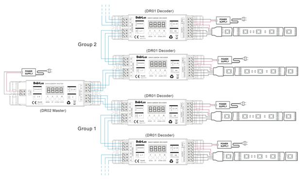
2) The controller has 2 groups equivalent output signals. When both of outputs are connected to the DMX / RDM signal amplifier, the RDM function will be invalid (the DMX function is normal);
3) The number of DMX / RDM amplifiers cascaded under cannot exceed 5 pcs, please refer to DR03 product description for more details.
6. Application
Product information for placing order
- Working voltage is DC12-24V;
- 2 groups output signal with same control effect;
- 4 in 1 functions for Single color/CCT/RGB/RGBW, different control effect to different LED types;
- Compatible with RDM protocols to identify the number of devices and change the device address;
- Adopts pushbuttons (MODE UP DOWN SAVE) to make setting and control, the 4-digital tube displays the setting statues intuitively;
- 3-year warranty.
| Working temperature | -20-60в„ғ | Supply voltage | DC12V~24V |
| Static power consumption | <1W | Output signal | DMX512/RDM |
| Net weight | 106g | Gross weight | 115g |
| Output gray | 100 levels | Speed of modes | 100 levels |
| External dimension | L162*W46*H25 (mm) | Packing size | L170*W50*H29 (mm) |
| Output ports | 2 groups | DMX profiles |
4 profiles PH01 for RGB LED(3 CH) PH02 for RGBW LED(4 CH) PH03 for CCT LED(3 CH) PH04 for Single color LED(1 CH) |

Interface Specifications


Use Instruction
| Button | Description | |
| MODE |
|
|
| UP | Increase the menu data entered by the MODE key, long press to quickly adjust. | In the OFF state, press the UP and DOWN keys for 2 seconds to enter the advanced settings page. |
| DOWN | Reduce the menu data entered by the MODE key, and long press to quickly adjust. | |
| SAVE |
|
|
In the power-on state, you can directly perform "basic settings", including control settings of mode / speed / brightness.
1) Mode setting
Turn on the power or press the "MODE" key briefly, when the digital tube displays Hxxx (xxx is determined by the effect), enter the setting page of mode. Press the "UP" / "DOWN" keys to set the effect. The effect is shown in the table below. Then press "SAVE" key to save and finish the operation(display SAVE 1 second and return to Hxxx).
2) Speed setting
By short pressing the "MODE" key, when the digital tube displays Sxxx (xxx is 000-255), enter the setting page of speed. Set the effect speed by short pressing the "UP" and "DOWN" keys. Then press the "SAVE" key to save and finish the operation (display SAVE for 1 second and return to Sxxx).
3) Brightness setting
By short pressing the "MODE" key, when the digital tube displays bxxx (xxx is 010-255), enter the setting page of brightness. Set the effect brightness by short-pressing (long-pressing the address quickly) "UP" and "DOWN" keys. Then press "SAVE" key to save and finish the operation (display SAVE 1 second and return to bxxx).
2. Advanced settings
In the Off state, press and hold the "UP" and "DOWN" keys for 2 seconds to enter the "Advanced Settings", can achieve the number of pixels and output type settings.
1) Set the number of pixels (number of devices)
By short pressing the "MODE" key, when the digital tube displays Pxxx (xxx for RGB is 005-170, RGBW for xxx is 005-128, CCT for xxx is 005-256, monochrome for xxx is 005-512), enter the setting The number of pixels. Select by short pressing the "UP" and "DOWN" keys, the minimum setting is 10. After setting, press the "SAVE" key (display SAVE 1 second and return to Hxxx) to save and exit the advanced settings.
2) Set the output type (PH01 is RGB, PH02 is RGBW, PH03 is CCT, and PH04 is monochrome).
By short pressing "MODE" key, when the digital tube displays PHxx (xx is 01-04), enter to set the output type. Select by short pressing the "UP" and "DOWN" keys. After setting, press the "SAVE" key (display SAVE 1 second and return to Hxxx) to save and exit the advanced settings.
Attachment: DR02 output type setting and DR01 decoding type setting coordination table
| LED type | DR02(master) | DR01(decoder) | DMX channels | DMX Address of DR01(assumes DMX start address of d001) |
| RGB | PH01 | CH01 | 3 | d001-d003; d004-d006; d007-d009…… |
| RGBW | PH02 | CH04 | 4 | d001-d004; d005-d008; d009-d0012…… |
| CCT | PH03 | CH04 | 4 | d001-d004; d005-d008; d009-d0012…… |
| Single color | PH04 | CH09 | 1 | d001; d002; d003…… |
In the power-on state, long press the "SAVE" button for about 2 seconds to enter the RDM function mode, you can achieve the search and address settings of the decoder, long press the "SAVE" button for 2 seconds to save and exit the RDM function after operation.
1) Search the decoder device through DR02
In the RDM function state, short press the "MODE" key, the digital tube displays Lxxx (xxx is 000-128, representing the number of decoders found). L000 means no device was found. For example, L032 means 32 decoders have been searched. At this time, by short pressing the "UP" and "DOWN" keys on the main control, the value on the digital display will increase or decrease accordingly, and at the same time, the load light on the decoder at the corresponding address will flash 2 times to confirm The current decoder position is Lxxx (xxx is 001-032, because only 32 devices are found). If the LED displays L008, the load light of the 8th decoder will flash twice.
2) Set the address of the decoder through DR02 (should be after the search and positioning operation; here L008 is used as an example for further explanation.)
After finding the L008 decoder (the load light of the L008 decoder flashes twice), press the "MODE" key on the main controlпјҲDR02пјү, the digital tube will display dxxx, which is the current DMX512 address of the decoder (L008). At this time, by short pressing the "UP" and "DOWN" keys, you can set the address of L008.
For example: Assuming that the initial DMX starting address of L008 is d001, it needs to be changed to d004 through the main DR02. That is, change the value on the digital tube from d001 to d004 by short pressing the "UP" and "DOWN" keys, and then press the "SAVE" key to save to complete the operation. Correspondingly, the digital tube of DR02 will display SAVE and return to d004. It means that the starting address of L008 decoder has been changed from d001 to d004.
If the starting address of the L008 decoder is changed on the decoder side, the digital tube display on the DR02 will also change in real time.
4. Mode table for different output type
1) Modes under PH01 for RGB
| No. | Mode | Marks | No. | Mode | Marks |
| 1 | Static red | Brightness is adjustable | 21 | Red right way chase | Speed is adjustable |
| 2 | Static green | 22 | Green left way chase | ||
| 3 | Static blue | 23 | Blue right way chase | ||
| 4 | Static yellow | 24 | White left way chase | ||
| 5 | Static purple | 25 | Red right way slide | ||
| 6 | Static cyan | 26 | Green right way slide | ||
| 7 | Static white | 27 | Blue right way slide | ||
| 8 | Red flash | Speed is adjustable | 28 | Yellow right way slide | |
| 9 | Green flash | 29 | Purple right way slide | ||
| 10 | Blue flash | 30 | Cyan right way slide | ||
| 11 | White flash | 31 | White right way slide | ||
| 12 | White right way stream | 32 | 7-color right way slide | ||
| 13 | 7-color right way stream | 33 | 7-color jump & right way slide | ||
| 14 | 7-color double way stream | 34 | 7-color right way refresh | ||
| 15 | 7-color opening | 35 | 7-color double way stream | ||
| 16 | 7-color closing | 36 | 7-color right way heap with 7-color background | ||
| 17 | 3-color jump | 37 | 7-color right way heap with white background | ||
| 18 | 7-color jump | 38 | Full color right way float | ||
| 19 | 3-color fade | 39 | 7-color right way flow | ||
| 20 | 7-color fade | 40 | 1-39 auto loop |
| No. | Mode | Marks | No. | Mode | Marks |
| 1 | Static red | Brightness is adjustable | 24 | RGBW fade | Speed is adjustable |
| 2 | Static green | 25 | 7-color fade | ||
| 3 | Static blue | 26 | Red right way chase | ||
| 4 | Static yellow | 27 | Green left way chase | ||
| 5 | Static purple | 28 | Blue right way chase | ||
| 6 | Static cyan | 29 | White left way chase | ||
| 7 | Static white (W) | 30 | Red right way slide | ||
| 8 | Static RGBW full light | 31 | Green right way slide | ||
| 9 | Red flash | Speed is adjustable | 32 | Blue right way slide | |
| 10 | Green flash | 33 | Yellow right way slide | ||
| 11 | Blue flash | 34 | Purple right way slide | ||
| 12 | White flash(W) | 35 | Cyan right way slide | ||
| 13 | RGBW full flash | 36 | White right way slide | ||
| 14 | RGBW full fade | 37 | 7-color right way slide | ||
| 15 | RGBW full stream | 38 | 7-color jump & right way slide | ||
| 16 | 7-color right way stream | 39 | 7-color right way refresh | ||
| 17 | 7-color double way stream | 40 | 7-color double way stream | ||
| 18 | 7-color opening | 41 | 7-color right way heap with 7-color background | ||
| 19 | 7-color closing | 42 | 7-color right way heap with white background | ||
| 20 | 3-color jump | 43 | Full color right way float | ||
| 21 | RGBW jump | 44 | 7-color right way flow | ||
| 22 | 7-color jump | 45 | 1-44 auto loop | ||
| 23 | 3-color fade |
| No. | Mode | Marks | No. | Mode | Marks |
| 1 | Static WW | Brightness is adjustable | 8 | WW/CW alternating chase | Speed is adjustable |
| 2 | Static CW | 9 | WW+CW chase | ||
| 3 | Static WW+CW | 10 | WW/CW alternating stream | ||
| 4 | WW/CW alternating flash | Speed is adjustable | 11 | WW/CW alternating double way stream | |
| 5 | WW+CW flash | 12 | WW+CW stream | ||
| 6 | WW/CW alternating fade | 13 | WW+CW double way stream | ||
| 7 | WW+CW fade | 14 | 1-13 auto loop |
| No. | Mode | Marks | No. | Mode | Marks |
| 1 | Static | Brightness is adjustable | 5 | Stream | Speed is adjustable |
| 2 | Flash | Speed is adjustable | 6 | Double way stream | |
| 3 | Fade | 7 | Segmented double way stream | ||
| 4 | Chase | 8 | 1-7 auto loop |
1) The RDM controller can search up to 128 devices (DMX/RDM decoder) in the Max.;
2) The controller has 2 groups equivalent output signals. When both of outputs are connected to the DMX / RDM signal amplifier, the RDM function will be invalid (the DMX function is normal);
3) The number of DMX / RDM amplifiers cascaded under cannot exceed 5 pcs, please refer to DR03 product description for more details.
6. Application

Product information for placing order
| Product name | Item number |
| DMX512/RDM Master | HX-DR02 |
| DMX512 RDM DECODER | HX-DR01 |
| DMX512 Signal Amplifier | HX-DR03 |
Product Video
Data download
Keywords:гҖҖжҺ§еҲ¶еҷЁ гҖҖled гҖҖи°ғ гҖҖHX-SZ600-TOUCH гҖҖHX-SZ600- гҖҖHX-RFBT002-RGB


 Jane-Hoion