HX-DMXCM-3CH
-
Product Introduction:
Before installing this product, please read this manual carefully to ensure that this specification is fully understood to avoid unnecessary damage and additional costs.
Product Details
Product Introduction
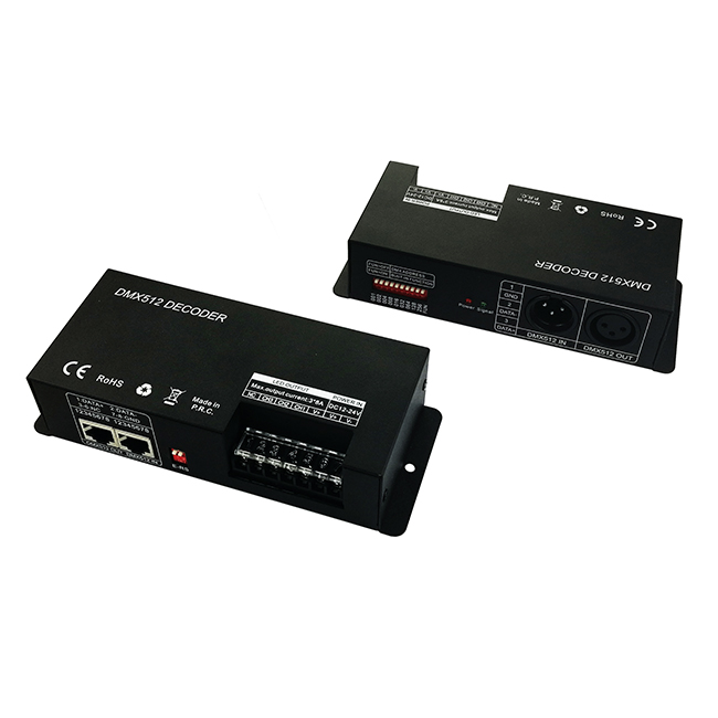
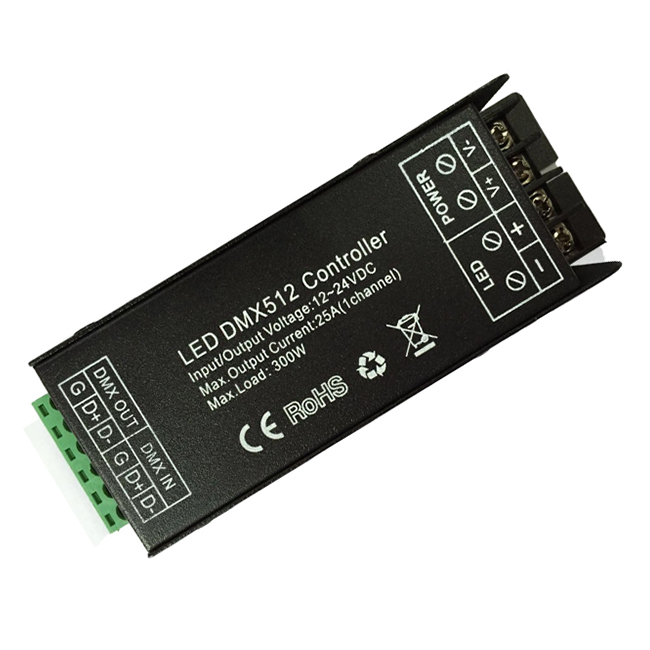
DMXCM-3CH is the constant voltage decoder, can accept the international widely-used DMX512 standard digital control signal, convert it into PWM signal to actuate LED RGB lighting; suitable for all kinds of constant voltage LED lamps, such as RGB LED module, LED strip, light string and so on; Decoders can be connected with signal line through network port or XLR plug to continue expanding the channel, and accept the manual-setting address by DIP switch, control different multiple decoders lighting effects through the DMX console; When the decoder is not connected with the DMX console, the machine can be set as master controller by DIP code, and multiple decoders can be sync-work.
Technical Parameters
Product Feature
1. The product is a constant voltage type controller, working voltage DC12-24V.
2. 3 Channels output, Max. Output current up to 8A per channel.
3. The product is hardware Bus-based, when all DIP switch is “0”, the address is “1”, could set channel address through the DIP switch as well.
4. With Power off memory function, each time power it, the last power-down mode will be retained.
5. When used alone as a controller, with 9 modes, which could be changed by DIP switch on controller, speed could be adjusted through DIP switch when static mode; multiple decoders and LED could be synchronized controlled.
6. To achieve more lighting synchronization in same area with the DMX decoder, could connect our company's RGB signal amplifier to expand power.
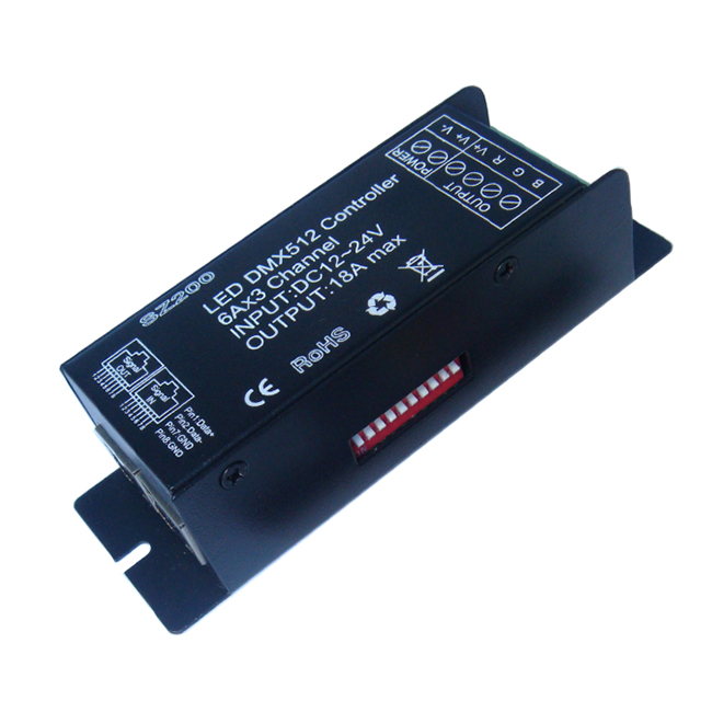
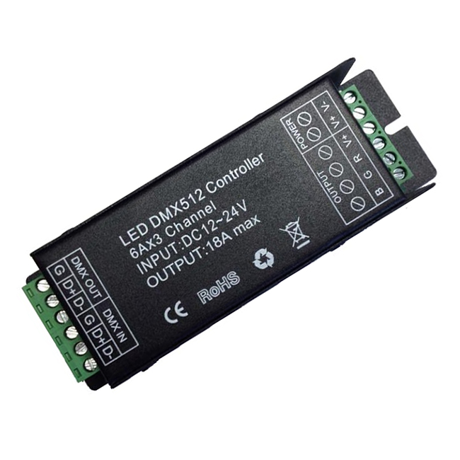
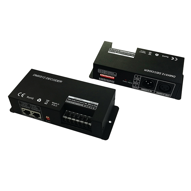
Interface Specifications
DMX Input, Output Interfaceпјҡ Network Interfaceпјҡ
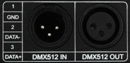
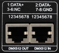
Standard XLR-3 Caron socket Standard cable RJ45 port
Address code and Function setting Interface: Power and load Interfaceпјҡ
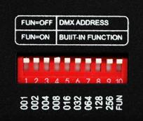
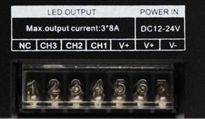
Adopt 10 bit site dial type DIP switch Adopt black column type terminal (with cap)
E-RS DIP switch Interfaceпјҡ

If the recoil effect occurs because of longer signal line or bad line quality, please try to take two E-RS switches on at the end of each line(the last one only) .
Use Instruction
This product compliance standard DMX 512 protocol, hardware bus-based set address manually;
Each DMX512 decoder occupies 3 DMX addresses, adopt DIP switch to set up address: When set up the address via DIP switch, the 10th DIP switch bit is “off” status, and other 9 DIP switch(1-9) bits are binary value code switch, which are used to set up the DMX starting address code. The first DIP switch’s bit is the lowest order bit, and the ninth’s is the highest order bit. That can set up 511 address codes. The DMX starting address code = (equal to ) sum of 1st to 9th bit. If move down the DIP switch (“ON” set as “1”), you can get the Bit value of this DIP switch. If move up (set as “0”), the bit value is 0. For example: if you want to set up DMX starting address code for 73, you should move down the 7th, 4th, and 1st DIP switch as “1”, and others as “0”, Then the bit value sum of 1st to 9th is 64+8+1. That is to say, the DMX512 starting address code is 73. (The correspondence dials code position is as follows)
Select Channel by DIP Switch:
1. Example 1:
Like figure 1, to set up the DMX starting address code for 37, should move down the 6th, 3rd, 1st DIP switch as“1”, others as “0”. Then the bit value sum of 1st to 9th DIP switch is 32+4+1, as is for 37.
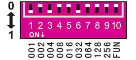
Figuire 1
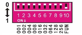
2. Example 2:
Like figure 2, to set up the DMX starting address code for 328, should move down the 9th, 7th, 4th DIP switch as“1”, others as “0”. Then the bit value sum of 1st to 9th DIP switch is 256+64+8, as is for 328.

Figure 2
Other function use Instruction
1. Function Test:
The10th DIP switch is “FUN”, for built-in function key. When “FUN”=”OFF”(up as 0), this product is for DMX decoder function, which adopt DMX signal; When “FUN”=”ON”(down as 1), this product is for master controller, which send the operating mode DMX signal to next decoder, so as to achieve multiple decoders synchronized controlled.
 The test function like figure 3:
1пјҚ9 Switch OFFпјҡblack
Switch 1пјқONпјҡRed
Switch 2пјқONпјҡGreen
Switch 3пјқONпјҡBlue
Switch 4пјқONпјҡYellow
Switch 5пјқONпјҡPurple
Switch 6пјқONпјҡCyan
Switch 7пјқONпјҡWhite Figure 3
Switch 8пјқONпјҡSeven-color jumpy changing (8 grades of speeds are available)
Switch 9пјқONпјҡAll-color gradual changing (8 grades of speeds are available)
2. Speed choice of jumpy changing and gradual changing’s effect:
When test function, switch 8=ON(down as 1), is for seven-color jumpy changing effect. When switch 9=ON, is for seven-color gradual changing effect. 8 grades of speeds are available for each effect:
 1пјҚ7 Switch OFFпјҡ0 grades of speeds
Switch 1пјқONпјҡ1 grades of speeds
Switch 2пјқONпјҡ2 grades of speeds
Switch 3пјқONпјҡ3 grades of speeds
Switch 4пјқONпјҡ4 grades of speeds
Switch 5пјқONпјҡ5 grades of speeds
Switch 6пјқONпјҡ6 grades of speeds
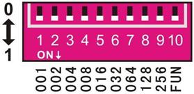
Switch 7пјқONпјҡ7 grades of speeds (Fast speed) Figure 4
 Like figure 4, when all switches are “ON” (down as 1) at the same time, the largest value bit is taken as final. That state of decoder is: All-color gradual changing, 7 grades of speeds changing. In addition, when signal indicator (green) blinks slowly, it runs the built-in program effectiveness of decoder. When signal indicator flash rapidly, the decoder receives the DMX signal.
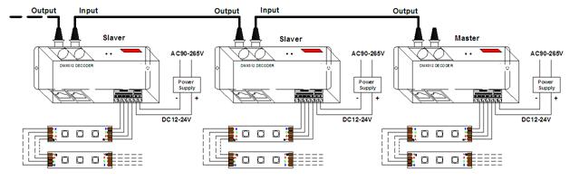
Typical Applications
Application 1:пјҲConnect with DMX Masterпјү
 Notice
1. This product supply voltage is DC12V~24V, don’t connect to other voltage.
2. The lead wire should be properly connected according to the connection diagram.
3. Overload may destroy the product, please avoid overload.
4. 3 years warranty, not including manual damage or overload work.
FAQ
Product information for placing order
DMXCM-3CH is the constant voltage decoder, can accept the international widely-used DMX512 standard digital control signal, convert it into PWM signal to actuate LED RGB lighting; suitable for all kinds of constant voltage LED lamps, such as RGB LED module, LED strip, light string and so on; Decoders can be connected with signal line through network port or XLR plug to continue expanding the channel, and accept the manual-setting address by DIP switch, control different multiple decoders lighting effects through the DMX console; When the decoder is not connected with the DMX console, the machine can be set as master controller by DIP code, and multiple decoders can be sync-work.
Technical Parameters
| Working temperature | -20-60в„ғ | Supply voltage | DC12V~24V |
| Static power consumption | <1W | Connecting mode | common anode |
| Net weight | 280g | Gross weight | 355g |
| Output gray | RGB each 256 level | Transmit signal | DMX signal |
| External dimension | L164*W66*H39 (mm) | Packing size | L183*W82*H62 (mm) |
| Output | 3 channels | Output current | <8A |
| Power off memory | Yes | Mode | 9 |
| Short circuit protection function | Yes | PWM frequency | 1.95KHZ |
| Output power | 12V:≤288W, 24V:≤576W | ||
1. The product is a constant voltage type controller, working voltage DC12-24V.
2. 3 Channels output, Max. Output current up to 8A per channel.
3. The product is hardware Bus-based, when all DIP switch is “0”, the address is “1”, could set channel address through the DIP switch as well.
4. With Power off memory function, each time power it, the last power-down mode will be retained.
5. When used alone as a controller, with 9 modes, which could be changed by DIP switch on controller, speed could be adjusted through DIP switch when static mode; multiple decoders and LED could be synchronized controlled.
6. To achieve more lighting synchronization in same area with the DMX decoder, could connect our company's RGB signal amplifier to expand power.
Interface Specifications
DMX Input, Output Interfaceпјҡ Network Interfaceпјҡ
Standard XLR-3 Caron socket Standard cable RJ45 port
Address code and Function setting Interface: Power and load Interfaceпјҡ
Adopt 10 bit site dial type DIP switch Adopt black column type terminal (with cap)
E-RS DIP switch Interfaceпјҡ
If the recoil effect occurs because of longer signal line or bad line quality, please try to take two E-RS switches on at the end of each line(the last one only) .
Use Instruction
This product compliance standard DMX 512 protocol, hardware bus-based set address manually;
Each DMX512 decoder occupies 3 DMX addresses, adopt DIP switch to set up address: When set up the address via DIP switch, the 10th DIP switch bit is “off” status, and other 9 DIP switch(1-9) bits are binary value code switch, which are used to set up the DMX starting address code. The first DIP switch’s bit is the lowest order bit, and the ninth’s is the highest order bit. That can set up 511 address codes. The DMX starting address code = (equal to ) sum of 1st to 9th bit. If move down the DIP switch (“ON” set as “1”), you can get the Bit value of this DIP switch. If move up (set as “0”), the bit value is 0. For example: if you want to set up DMX starting address code for 73, you should move down the 7th, 4th, and 1st DIP switch as “1”, and others as “0”, Then the bit value sum of 1st to 9th is 64+8+1. That is to say, the DMX512 starting address code is 73. (The correspondence dials code position is as follows)
Select Channel by DIP Switch:
| Decimals | 1 | 2 | 3 | 4 | 5 | 6 | 7 | 8 | 9 | 10 |
| Weightnumber | 1 | 2 | 4 | 8 | 16 | 32 | 64 | 128 | 256 | FUN |
Like figure 1, to set up the DMX starting address code for 37, should move down the 6th, 3rd, 1st DIP switch as“1”, others as “0”. Then the bit value sum of 1st to 9th DIP switch is 32+4+1, as is for 37.
Figuire 1
2. Example 2:
Like figure 2, to set up the DMX starting address code for 328, should move down the 9th, 7th, 4th DIP switch as“1”, others as “0”. Then the bit value sum of 1st to 9th DIP switch is 256+64+8, as is for 328.
Figure 2
Other function use Instruction
1. Function Test:
The10th DIP switch is “FUN”, for built-in function key. When “FUN”=”OFF”(up as 0), this product is for DMX decoder function, which adopt DMX signal; When “FUN”=”ON”(down as 1), this product is for master controller, which send the operating mode DMX signal to next decoder, so as to achieve multiple decoders synchronized controlled.
The test function like figure 3:1пјҚ9 Switch OFFпјҡblack
Switch 1пјқONпјҡRed
Switch 2пјқONпјҡGreen
Switch 3пјқONпјҡBlue
Switch 4пјқONпјҡYellow
Switch 5пјқONпјҡPurple
Switch 6пјқONпјҡCyan
Switch 7пјқONпјҡWhite Figure 3
Switch 8пјқONпјҡSeven-color jumpy changing (8 grades of speeds are available)
Switch 9пјқONпјҡAll-color gradual changing (8 grades of speeds are available)
2. Speed choice of jumpy changing and gradual changing’s effect:
When test function, switch 8=ON(down as 1), is for seven-color jumpy changing effect. When switch 9=ON, is for seven-color gradual changing effect. 8 grades of speeds are available for each effect:
1пјҚ7 Switch OFFпјҡ0 grades of speedsSwitch 1пјқONпјҡ1 grades of speeds
Switch 2пјқONпјҡ2 grades of speeds
Switch 3пјқONпјҡ3 grades of speeds
Switch 4пјқONпјҡ4 grades of speeds
Switch 5пјқONпјҡ5 grades of speeds
Switch 6пјқONпјҡ6 grades of speeds
Switch 7пјқONпјҡ7 grades of speeds (Fast speed) Figure 4
Like figure 4, when all switches are “ON” (down as 1) at the same time, the largest value bit is taken as final. That state of decoder is: All-color gradual changing, 7 grades of speeds changing. In addition, when signal indicator (green) blinks slowly, it runs the built-in program effectiveness of decoder. When signal indicator flash rapidly, the decoder receives the DMX signal.Typical Applications
Application 1:пјҲConnect with DMX Masterпјү
- An amplifier is needed when more than 32 decoders are connected, signal amplification should not be more than 5 times continuously.
- If the recoil effect occurs because of longer signal line or bad line quality, please try to take two E-RS switches on at the end of each line(the last one only) .
Notice1. This product supply voltage is DC12V~24V, don’t connect to other voltage.
2. The lead wire should be properly connected according to the connection diagram.
3. Overload may destroy the product, please avoid overload.
4. 3 years warranty, not including manual damage or overload work.
FAQ
| Problem | Possible reason | Solution |
| 1. Light off after power on | bad connection with power supply or no output power from power supply | Connect wire with power supply well or change power supply |
| Power supply line not connect well or short circuit | connect power supply wire line well | |
|
2. Not work after connecting some loads |
Overload and burn out some components of controller | Change the component or change controller |
| 3. Synchronization not work after one of controllers | Signal line loose | reconnect signal line |
| Product name | Item number |
| 3CH DMX512 decoder | HX-DMXCM-3CH |
Product Video
Data download

Keywords:гҖҖжҺ§еҲ¶еҷЁ гҖҖled гҖҖи°ғ гҖҖHX-SZ600-TOUCH гҖҖHX-SZ600- гҖҖHX-RFBT002-RGB
 Jane-Hoion